Many standard products originate from a “custom” request. Please inquire if your measurement needs are not fully met. Some examples of our development projects include:
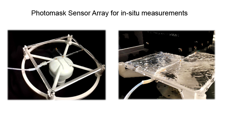
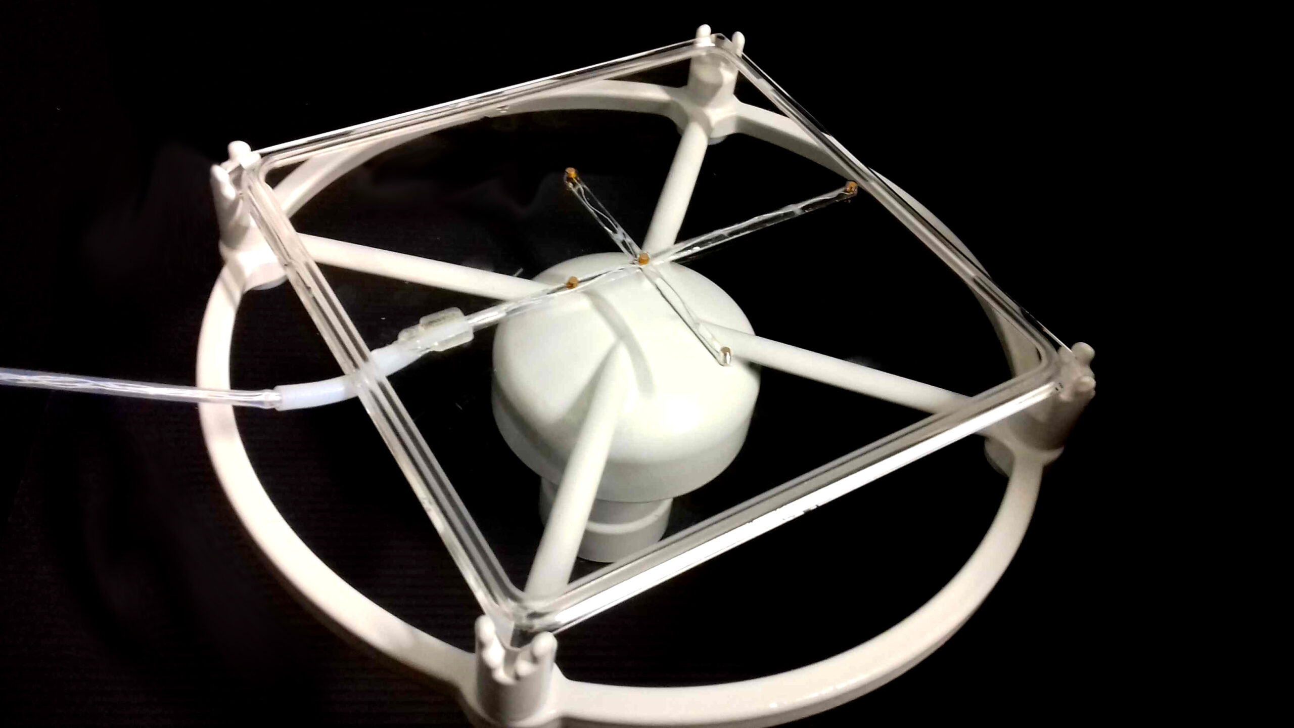
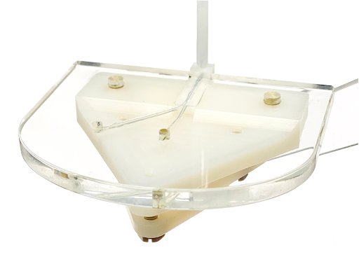
Shrinking process windows for advanced megasonic photomask cleaning are demanding a zero-defect process requirement. To correlate acoustic parameters with cleaning performance, an in-situ measurement of the acoustic field is required. Wired cavitation sensor arrays are being developed to understand how cavitation behaves with frequency, generator power, and transducer distance. Meanwhile, wireless cavitation sensor arrays can characterize the dynamic effects of the mask rotation, transducer arm speed, and exposure time.
“Check sensors” are designed to monitor the acoustic output from nozzle and skirt transducers used for single wafer and photomask cleaning processes. When connected with the MCT meters, digital logging allows immediate detection of any process excursions.
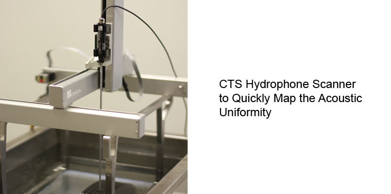
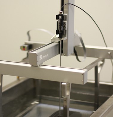
Automate scanners can map the tank uniformity with higher productivity than manual movements, allowing high resolution measurements to be made. With a small HCT shaft diameter (3 mm), two-dimensional acoustic plots can be acquired in “loaded” configurations to simulate actual conditions in the cleaning process (e.g., between substrates for semiconductors, data storage, and related applications).
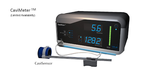
The novel cavitation detector developed by National Physical Laboratory (NPL) is designed to measure both the broadband acoustic signal generated from cavitation and the direct field at the drive frequency in the ultrasonic cleaning tank. The hollow cylindrical shaped CaviSensor is constructed where both the HF and LF signals are separated, and then processed by the CaviMeter to quantify both the level of cavitation and direct field pressure. While the availability of the CaviMeter is limited, the MCT meters rely on the same measurement principles.
There are two main components: (1) the hydrophone to detect the acoustic pressure and (2) the meter to process the acoustic signal.
When selecting the hydrophone, factors such as the frequency range, chemistry compatibility, robustness, size, and cost must all be taken into account. The HCT hydrophone has a wide bandwidth and can support frequencies up to 1.2 MHz. The shaft material is Teflon and is compatible with a broad range of chemistries. Finally, the HCT has an outer diameter of 3 mm and the sensing element is mechanically isolated from the shaft to localize measurements to a point.
To select the right meter depends on the importance of absolute versus relative measurements. Process control use-cases may consist of multiple production lines across different facilities and require absolute measurements to directly compare one tank to another. In this case, a calibrated MCT-2000 may be more suitable. Relative measurements with the MCT-1200 may be adequate for quick spot checks or studies to characterize process trends (e.g., time).
Another factor is the need to quantify the cavitation performance. For R&D and process control, it may be useful to acquire lower-level transient and stable cavitation data to develop, tune, and monitor a process.
Both hydrophones are compatible with either meter. The cavitation meter does require a hydrophone calibration.
Please review a product comparison chart HERE.
To evaluate the performance of an ultrasonic system (e.g., cleaning tank), one must take into account the relationships between voltage, pressure, intensity, power, and frequency.
Hydrophones are designed to measure the mechanical sound pressure in water. Most hydrophone sensors are piezoelectric materials which convert mechanical energy to electrical energy. The acoustic pressure (Pa) detected is converted to a voltage output (V) which can be acquired and analyzed with an instrument such as the MCT-2000 cavitation meter, MCT-1200 pressure meter, or even an oscilloscope.
Because each hydrophone has an inherent frequency response, an acoustic calibration of the hydrophone determines the sensitivity as a function of frequency. This is measured in units of electrical output per unit of physical pressure (V/Pa) over a frequency range (Hz) and is traceable to a primary calibration laboratory. Only with a calibration is it possible to make absolute measurements of physical pressure.
The acoustic waveform is the acoustic pressure as a function of time. By post-processing the waveform, the total pressure can be separated into the direct field and cavitation pressure. Click HERE for further information about how the pressure components are determined.
The acoustic intensity or acoustic power density (W/cm2) is the product of pressure and velocity at any location. Since particle velocity can be measured only under very specific conditions (typically not an ultrasonic tank), the approximation that velocity is the pressure divided by the impedance of the medium is commonly used. However, this approximation is only valid when away from the source – and when the wave propagates “cleanly” without the presence of reflections.
Ultrasonic systems consist of a transducer driven by electronics, such as a generator. The drive electronics delivers electrical power (W) to the transducers to generate the acoustic field. The efficiency () of an ultrasonic system can be estimated as the acoustic power inside the vessel divided by the electrical power delivered to the transducer. The efficiency for each ultrasound system will vary since it depends on many design factors.
For additional information about measurement units, please refer to HERE.
Typically, hydrophones are calibrated annually.
Each Onda hydrophone includes an acoustic calibration certificate which follows IEC 62127-2, by performing the calibration by comparison to a reference hydrophone whose calibration is traceable to NPL. The detailed calibration method is described HERE.
A copy of a traceability certificate for calibrations of hydrophones and preamplifiers at Onda is available upon request.
It may be useful to work backwards.
Two parameters commonly used to control a cleaning process include the particle removal efficiency (PRE) and the localized damage. These parameters are often determined by visual, optical, or chemical methods, counting and binning particle or defect information. To translate these parameters to the acoustic performance, a correlation study to determine how process variables such as frequency, generator power, chemistry, temperature etc. influence the acoustic parameters including the direct field, stable cavitation, and transient cavitation pressure.
For reference, there are published studies available HERE.
Our dedicated specialists are ready to assist you in discovering the ideal product or part for your specific needs. Reach out via phone or email, and we’ll ensure you get precisely what you need for the task at hand.